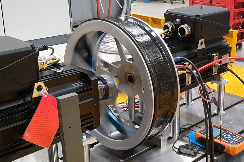
TK motors combine high torque and high-speed capabilities, enabling them to work as both spindle and rotary table motors. Thanks to this dual function, they offer greater adaptability, making them ideal for various industrial applications. As a result, users benefit from improved efficiency, flexibility, and consistent performance in a single, precision-driven system.
TK motor rotors use special Phase-manufactured magnets to ensure efficient high-speed operation with minimal energy loss. This advanced design not only boosts performance but also improves reliability, making these motors ideal for demanding and high-precision environments. In turn, users enjoy greater productivity and reduced downtime.
TK motors are built as three-phase rare-earth (Iron Neodymium Boron) permanent magnet units, offering a balance of strength and efficiency. This construction allows them to deliver exceptional continuous and peak torque density, meeting the needs of high-performance applications.
Moreover, their design supports precise speed and flux control over a constant power range of up to 10:1. Consequently, they handle varying loads while maintaining stable and consistent performance, making them perfect for dynamic and precision-based operations.
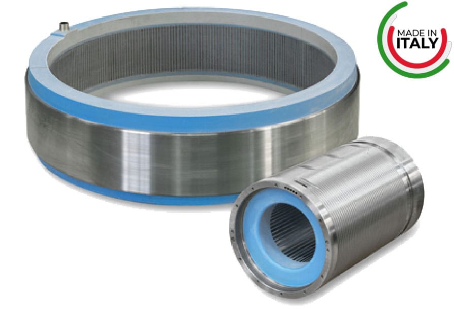
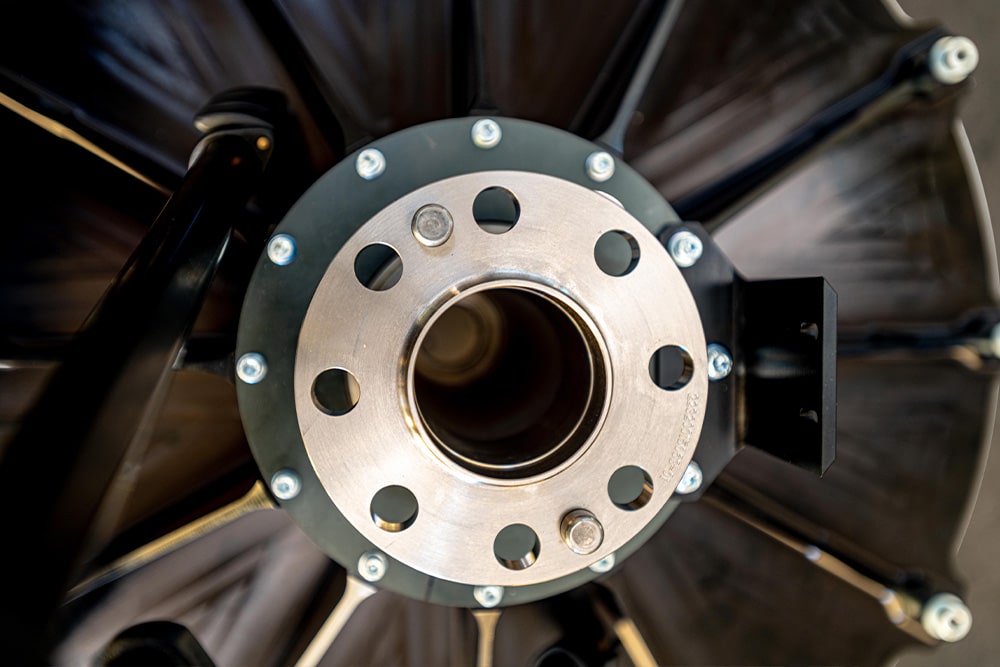
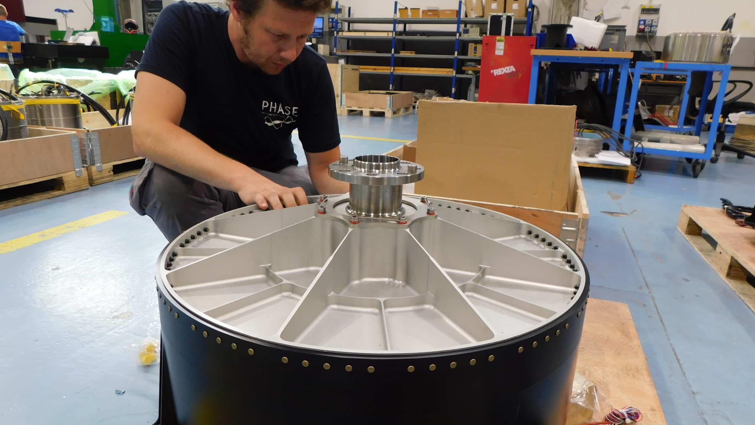
TK Torque Motors are provided as separate stator and rotor units, allowing for direct mounting inside machine structures. This simple setup not only simplifies installation but also ensures strong and reliable performance.
In addition, their robust construction—featuring glue-free magnet retention and preloaded carbon fiber sleeves—ensures safe operation, even at very high speeds. As a result, the design reduces wear and extends the motor’s lifespan.
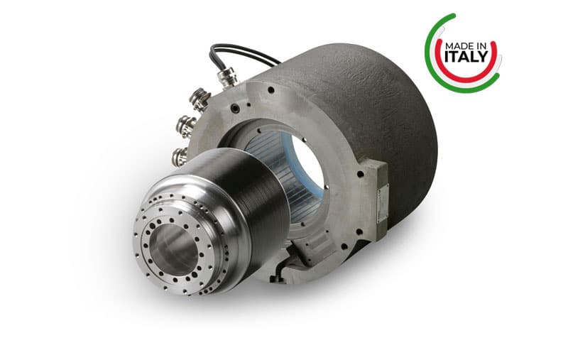
But there’s more. TK motors offer customization options to meet specific application needs. Users can choose semi-custom rotors and frames with integrated cooling systems for enhanced efficiency. Ultimately, this flexibility makes TK motors a great fit for industries requiring precision, power, and reliability.
Torque Motors with Direct Drive Tecnology in Frameless Configuration leads to
3D and CAD drawings of torque motors TK series are available for the best integration in engineering, design, virtual commissioning, digital twin projects, in

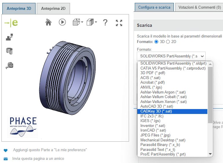 * Motor/size/type/options choice with draw preview in the 3D Web Viewer with all typical functions like measure, rotation, sections and orientation
| Torque Motor code | Stack [mm] | L tot.[mm] | Øout [mm] | Øin [mm] | Torque (Water Cooled) [Nm] | Torque (Air Cooled)[Nm] | Peak Torque [Nm] |
Nominal Speed (rpm) | Max Speed (rpm) |
| TK.085 | 50 | 110 | 96 | 44 | 7,30 | 3,70 | 24,10 | 5000 | 18000 |
| 100 | 160 | 96 | 44 | 16,20 | 8,10 | 48,20 | |||
| 150 | 210 | 96 | 44 | 25,40 | 12,70 | 72,30 | |||
| 200 | 260 | 96 | 44 | 34,70 | 17,40 | 96,40 | |||
| TK.110 | 50 | 125 | 121 | 43 | 12,50 | 6,30 | 33,20 | 5000 | 20000 |
| 100 | 175 | 121 | 43 | 26,90 | 13,50 | 66,30 | |||
| 150 | 225 | 121 | 43 | 41,60 | 20,80 | 99,50 | |||
| 200 | 275 | 121 | 43 | 56,30 | 28,20 | 132,70 | |||
| TK.120 | 50 | 125 | 134 | 54 | 21,90 | 11,00 | 47,50 | 5000 | 15000 |
| 100 | 175 | 134 | 54 | 48,20 | 24,10 | 95,10 | |||
| 150 | 225 | 134 | 54 | 75,10 | 37,60 | 142,60 | |||
| 200 | 275 | 134 | 54 | 102,40 | 51,20 | 190,00 | |||
| TK.164 | 50 | 125 | 173 | 76 | 48,30 | 24,10 | 93,50 | 4000 | 10000 |
| 100 | 175 | 173 | 76 | 104,70 | 52,30 | 187,00 | |||
| 150 | 225 | 173 | 76 | 162,10 | 81,10 | 280,40 | |||
| 200 | 275 | 173 | 76 | 219,90 | 110,00 | 374,00 | |||
| 300 | 375 | 173 | 76 | 336,00 | 168,00 | 560,90 | |||
| TK.188 | 50 | 140 | 202 | 80 | 34,80 | 17,40 | 119,50 | 6000 | 28000 |
| 100 | 90 | 202 | 80 | 79,10 | 39,50 | 238,90 | |||
| 150 | 240 | 202 | 80 | 125,80 | 62,90 | 358,40 | |||
| 200 | 290 | 202 | 80 | 173,60 | 86,80 | 477,80 | |||
| 300 | 390 | 202 | 80 | 270,50 | 135,20 | 716,80 | |||
| TK.195 | 50 | 160 | 207 | 76 | 49,50 | 24,80 | 93,50 | 2000 | 15000 |
| 100 | 210 | 207 | 76 | 108,69 | 54,30 | 187,00 | |||
| 150 | 260 | 207 | 76 | 169,20 | 84,60 | 280,40 | |||
| 200 | 310 | 207 | 76 | 230,20 | 115,00 | 374,00 | |||
| 300 | 410 | 207 | 76 | 352,70 | 176,40 | 560,90 | |||
| TK.220 | 50 | 170 | 240 | 110 | 75,60 | 37,80 | 159,00 | 3000 | 14000 |
| 100 | 220 | 240 | 110 | 172,40 | 86,20 | 318,10 | |||
| 150 | 270 | 240 | 110 | 274,40 | 137,20 | 477,10 | |||
| 200 | 320 | 240 | 110 | 378,70 | 189,30 | 636,20 | |||
| 300 | 420 | 240 | 110 | 590,10 | 295,10 | 954,30 | |||
| TK.240 | 50 | 135 | 249 | 142 | 111,20 | 55,60 | 216,50 | 3000 | 8000 |
| 100 | 185 | 249 | 142 | 240,00 | 120,00 | 433,00 | |||
| 150 | 235 | 249 | 142 | 371,30 | 185,60 | 649,40 | |||
| 200 | 285 | 249 | 142 | 465,90 | 251,60 | 865,90 | |||
| TK.270 | 50 | 140 | 282 | 160 | 112,30 | 56,20 | 282,70 | 3000 | 8000 |
| 100 | 190 | 282 | 160 | 253,00 | 126,50 | 565,50 | |||
| 150 | 240 | 282 | 160 | 399,30 | 199,60 | 848,20 | |||
| 200 | 290 | 282 | 160 | 547,70 | 273,90 | 1.131,00 | |||
| TK.310 | 50 | 120 | 310 | 198 | 215,60 | 107,80 | 373,90 | 500 | 3000 |
| 100 | 170 | 310 | 198 | 475,90 | 238,00 | 748,00 | |||
| 150 | 220 | 310 | 198 | 743,30 | 371,70 | 1.121,80 | |||
| 200 | 270 | 310 | 198 | 1.013,00 | 506,60 | 1.495,70 | |||
| TK.340 | 50 | 145 | 358 | 190 | 242,00 | 121,00 | 407,20 | 2000 | 6000 |
| 100 | 195 | 358 | 190 | 547,20 | 273,60 | 814,30 | |||
| 150 | 245 | 358 | 190 | 864,70 | 432,40 | 1.221,50 | |||
| 200 | 295 | 358 | 190 | 1.186,90 | 593,50 | 1.628,60 | |||
| 300 | 395 | 358 | 190 | 1.837,00 | 918,50 | 2.442,90 | |||
| TK.370 | 50 | 140 | 380 | 268 | 271,70 | 135,90 | 636,20 | 1000 | 4000 |
| 100 | 190 | 380 | 268 | 604,50 | 302,20 | 1.272,30 | |||
| 150 | 240 | 380 | 268 | 947,40 | 473,70 | 1.908,50 | |||
| 200 | 290 | 380 | 268 | 1.294,00 | 647,00 | 2.544,70 | |||
| 300 | 390 | 380 | 268 | 1.991,40 | 995,70 | 3.817,00 | |||
| TK.450 | 50 | 170 | 465 | 320 | 468,20 | 234,10 | 916,10 | 1000 | 3000 |
| 100 | 220 | 465 | 320 | 1.033,70 | 516,90 | 1.832,20 | |||
| 150 | 270 | 465 | 320 | 1.613,00 | 806,50 | 2.748,30 | |||
| 200 | 320 | 465 | 320 | 2.196,90 | 1.098,40 | 3.664,40 | |||
| TK.485 | 50 | 145 | 485 | 345 | 544,00 | 213,00 | 1.068,00 | 1000 | 2000 |
| 100 | 195 | 485 | 345 | 1.197,00 | 500,00 | 2.136,00 | |||
| 150 | 245 | 485 | 345 | 1.858,00 | 802,00 | 3.204,00 | |||
| 200 | 295 | 485 | 345 | 2.521,00 | 1.110,00 | 4.272,00 | |||
| TK.540 | 50 | 145 | 548 | 400 | 712,80 | 356,40 | 1.431,40 | 400 | 1500 |
| 100 | 195 | 548 | 400 | 1.547,50 | 773,80 | 2.862,80 | |||
| 150 | 245 | 548 | 400 | 2.397,40 | 1.198,70 | 4.294,20 | |||
| 200 | 295 | 548 | 400 | 3.252,00 | 1.626,00 | 5.725,60 | |||
| TK.570 | 50 | 115 | 578 | 450 | 745,40 | 372,70 | 1.767,10 | 400 | 1500 |
| 100 | 165 | 578 | 450 | 1.673,00 | 836,50 | 3.534,30 | |||
| 150 | 215 | 578 | 450 | 2.632,50 | 1.316,20 | 5.301,40 | |||
| 200 | 265 | 578 | 450 | 3.603,60 | 1.801,80 | 7.068,60 | |||
| TK.795 | 50 | 160 | 815 | 640 | 1.631,10 | 815,50 | 3.365,40 | 200 | 800 |
| 100 | 210 | 815 | 640 | 3.781,20 | 1.890,60 | 6.730,70 | |||
| 150 | 260 | 815 | 640 | 6.063,60 | 3.031,80 | 10.096,10 | |||
| 200 | 310 | 815 | 640 | 8.402,10 | 4.201,10 | 13.461,40 | |||
| TK.1150 | 50 | 190 | 1210 | 908 | 3.495,00 | 1.785,00 | 6.789,00 | 100 | 400 |
| 100 | 240 | 1210 | 908 | 7.996,00 | 4.281,00 | 13.577,00 | |||
| 150 | 290 | 1210 | 908 | 12.696,00 | 6.952,00 | 20.366,00 | |||
| 200 | 340 | 1210 | 908 | 17.457,00 | 9.695,00 | 27.155,00 | |||
| TK.1340 | 50 | 190 | 1420 | 1100 | 4.542,80 | 2.271,40 | 9.842,30 | 100 | 400 |
| 100 | 240 | 1420 | 1100 | 10.639,40 | 5.319,70 | 19.684,60 | |||
| 150 | 290 | 1420 | 1100 | 17.147,10 | 8.573,50 | 29.526,90 | |||
| 200 | 340 | 1420 | 1100 | 23.831,50 | 11.915,70 | 39.369,20 | |||
| TK.1700 | 50 | 190 | 1770 | 1420 | 8.113,80 | 4.056,90 | 15.946,80 | 100 | 300 |
| 100 | 240 | 1770 | 1420 | 18.951,20 | 9.475,60 | 31.893,50 | |||
| 150 | 290 | 1770 | 1420 | 30.480,20 | 15.240,10 | 47.840,30 | |||
| 200 | 340 | 1770 | 1420 | 42.301,80 | 21.150,90 | 63.787,00 | |||
| TK.2000 | 50 | 260 | 2085 | 1700 | 8.587,40 | 4.293,70 | 23.004,10 | 100 | 300 |
| 100 | 310 | 2085 | 1700 | 20.713,90 | 10.356,90 | 46.008,20 | |||
| 150 | 360 | 2085 | 1700 | 34.103,80 | 17.051,90 | 69.012,30 | |||
| 200 | 410 | 2085 | 1700 | 48.132,40 | 24.066,20 | 92.016,40 | |||
| TK.3080 | 50 | 260 | 3170 | 2760 | 24.318,60 | 12.159,30 | 51.035,20 | 100 | 250 |
| 100 | 310 | 3170 | 2760 | 57.331,50 | 28.665,80 | 102.070,30 | |||
| 150 | 360 | 3170 | 2760 | 92.790,20 | 46.395,10 | 153.105,50 | |||
| 200 | 410 | 3170 | 2760 | 129.340,00 | 64.670,00 | 204.140,70 |


Home » Torque Motors » TK Torque Motors